|
|
|
|
|
Ferry van Eeuwen
|

|
Ondina's Radars
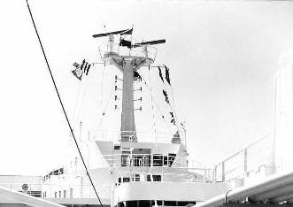
The ship was equipped with radar equipment manufactured by Raytheon Copenhagen. The radar system consisted of a 3 cm Raytheon 1602 and a 10 cm 1605 radars. The transmitter pulse power was respectively 45 kW and 60 kW. The supplier Radio Holland bv developed and supplied an additional interswitch system which was a major upgrade and made the radars state of the art and a show piece.
Both 3 cm and 10 cm Raytheon radar scanners were mounted on top op the radar mast amidships. The aerials, with slotted wave guides fitted inside, measured 12 feet each. The advantages and disadvantages of the 3 and 10 cm radar systems are explained below.
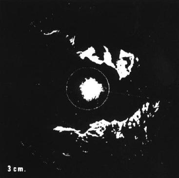
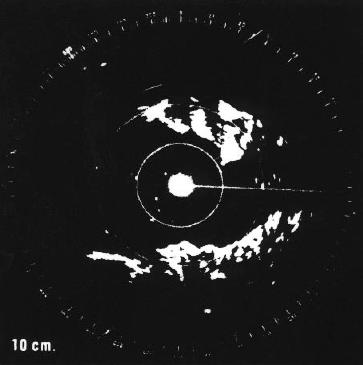
Their is a rather big difference in picture presentation between a 3 cm and a 10 cm wavelength radar signal. A big advantage of a 10 cm radar is that it can penetrate more easily through sea clutter (echoes returned from a choppy sea for instance) and rain storms. If the wavelength is big compared to the rain drops less false echoes are reflected from the rain drops. However a 3 cm radar picture has better detailed picture. The 10 cm radar is more of a bad weather radar system. The above pictures show two identical 20 mile range Planned Position Indicator (PPI) on Raytheon 3 cm and 10 cm radars showing the effects of sea clutter. On the 10 cm radar targets inside the 5 mile range marker ring are clearly visible. On the 3 cm radar the close range targets are missing totally which can lead to a very dangerous situation.
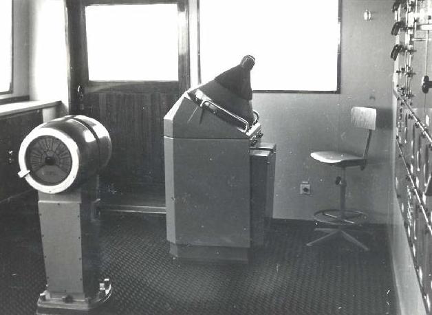
The Raytheon indicator with viewing hood was located at the starboard side of the wheel house. For better viewing during night time the rubber visor and the metal one underneath could be removed.
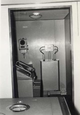
A picture of the radar plotting room which was located just behind the wheel house and adjacent to the chart room. To the left is the radar indicator and the box attached to the bulkhead is the interswitch. The smaller unit above the indicator is the compass repeater. The plotting room could be closed by heavy black curtains for daylight plotting purposes. By means of the interswitch unit you could connect the plotting indicator either to the 3cm or 10 cm radar transmitter. In the picture you can also see a part of the chart table. The little 'port hole' is mounted just over the chronometer which was very important to navigation in those non GPS days.
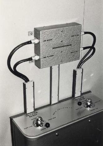
This is the interswitch unit as developed by Radio Holland's famous radar technician Piet Gouweleeuw at the Rotterdam office. The switch to the left switches the indicator and the one to the right the 3 and 10 cm radar transmitters.
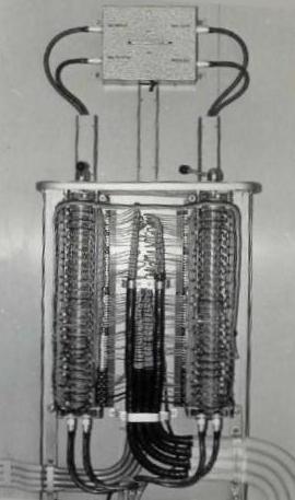
A view of the inside of the interswitch unit. Lots of cables running towards and from this unit necessary to realise the full interswitching of indicators and transmitters.
|